


A few suggestions by Yamaha IM regarding the surface-mount assembly using the latest 0201 mm chip capacitors and resistors, examining improvements in placement and inspection that enable manufacturers to achieve high yields and high quality when working with today’s smallest devices.
Mounting Accuracy and Correction Systems
Accurate component pickup holds the key to satisfactory placement, and is dependent on correct alignment of the nozzle and feeder, as well as correct pickup height. When picking up small chip resistors or capacitors, there is minimal tolerance for any offset between the centre of the component and the centre of the nozzle.
On-board automatic accuracy compensation systems correct errors due to factors such as feeder alignment, temperature change, and machine-related tolerances. Yamaha’s Multi-Accuracy Compensation System (MACS) uses machine vision to identify the centre of the component and compare its position with the centre of the nozzle to correct for deviations. This can reduce positional error from about 30 µm to less than 10 µm (3 sigma).
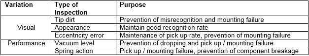
It is also worth noting that the correct nozzle for picking up 0201 mm components has a bore of just 0.1 mm, and can easily become blocked. Because visual inspection of such small features is often impractical, automatic nozzle health checking on-board Yamaha YS series mounters visually inspects the nozzle using side-view and upward-looking cameras, and checks pickup performance. Table 1 describes elements of the nozzle health check.
Automatic cleaning of all nozzles simultaneously, using a cleaner such as the SAWA Nozzle Cleaning Unit with built-in ultrasonic cleaning, can be effective and efficient. After cleaning, the entire bank of nozzles is reinstalled and aligned in a single operation.
Automatic pickup height teaching is also recommended to stabilize the pickup process for greater accuracy. Historically, the pickup height has been determined by calculation based on manually measuring the carrier tape thickness. To ensure stable pickup capability and prevent damage to vulnerable 0201mm chips, Yamaha’s automatic pickup-height learning system now measures the actual height of the feeder tape by bringing the nozzle into contact with the feeder tape and monitoring the change in negative pressure.
Inspection
Finally, the smaller-size parts challenge today’s inline automatic optical inspection (AOI) systems to achieve adequate image resolution without reducing the field of view and consequently extending the inspection cycle time.
Inline AOI systems in common use today have a camera sensor of about 5-Mpixels. These typically have a field of view that results in image resolution being about 18 μm. This is not good enough to provide an image of 0201 mm parts that can be analyzed easily and accurately.
Without changing the camera, the only way to increase the resolution is to reduce the field of view. This means a greater number of images must be taken to complete the inspection routine, which results in longer cycle time.
The latest systems, such as Yamaha’s 12 Mpixel YSi-V series, feature high-Mpixel cameras allow high-speed, high-precision inspection with a large field of view and selectable resolution of 12 μm or 7 μm. This is adequate for inspecting 0201 mm component alignment and solder-joint quality.
Moreover, inspection can be boosted by also applying multi-dimensional and multi-angle inspection. Yamaha’s YSi-V series is capable of 3D and 2D visual inspection, at each of four different angles and in red, blue and green wavelengths, to give a multi-direction view of each component. Additional built-in features include laser checking for coplanarity and component-height. Users can select from various imaging and detection methods, depending on the requirements of each individual application. Figure 2 shows how high-quality inspection images can be achieved through a combination of high-resolution camera and 3D imaging.
Conclusion
0201 mm SMD chip components are coming, and will demand far greater precision throughout printing, placement and inspection processes. At the same time, proper provisions must be made for other, larger components that are to be mounted on the same board.
A combination of process innovations such as two-stage screen printing, new materials like Type 5.5 pastes, and advanced mounter technologies including nozzle health checking, accuracy compensation, and high-Mpixel AOI with 3D imaging can make high-quality, high-throughput commercial assembly possible.


